
Restoration of a Millers Falls Boring Machine - Part 2
The restoration process
Three videos posted on the Internet show the restoration of boring machines where either rust remover or wire-brush wheels on a grinder were used to remove grease and paint/japanning¹,²,³. The author at some point will restore the boring machine in this manner but, for the moment, will pursue a less aggressive cleanup because he has a timber framing project that needs to be done. Rather than delaying the project to take the time to paint the parts, the cleanup described here was done in a manner to preserve the remaining paint or japanning until that more aggressive approach is taken. The main goals include cleaning up old grease and dirt that had accumulated on the machine and replacing old lubrication in the moving parts with fresh lubricant to make its operation easier and to reduce wear. The restoration includes what might be considered two separate projects: (1) the wood base, and (2) the boring mechanism.
Wood Base Restoration
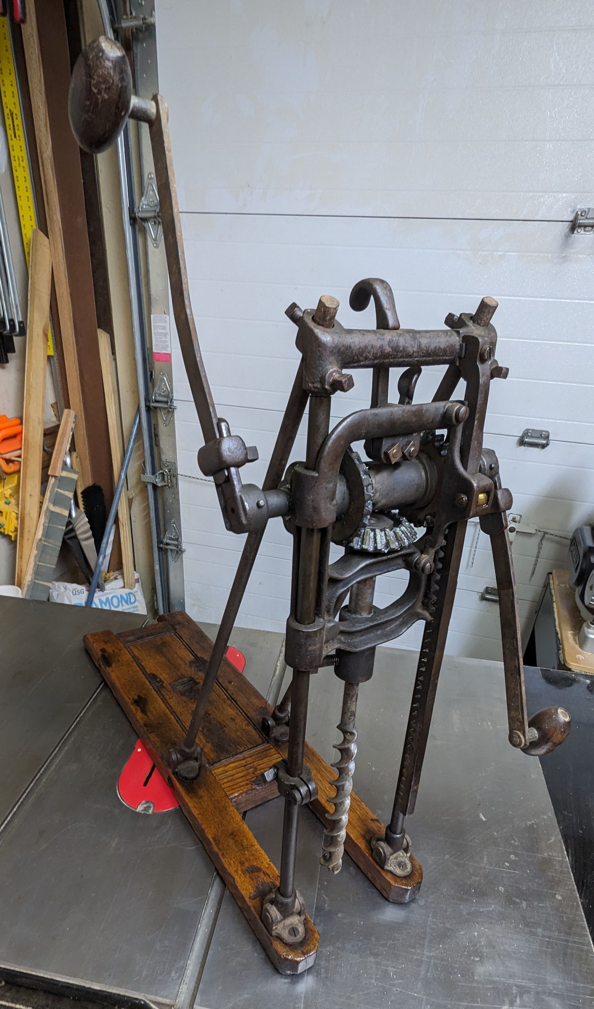
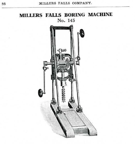
The bases of most boring machines are made of wood and, in the case of Millers Falls machines, the four support rods are screwed or bolted to the base, with two fasteners per rod. (Some later Millers Falls boring machines such as the No. 146 in the 1915 catalog had steel bases, although these seem to be rare.) The base and support rods, together, provide a stable drilling angle, while the adjustment of the support rods in reference to the base determines the angle of the bit relative to the base and the timber. A user’s weight on the base holds the base fast to a timber. The Millers Falls wooden base is constructed of five pieces, as shown in Figure 5. Two longer pieces receive the rod brackets, while two shorter pieces meet with those longer pieces at 90°. These four pieces frame the fifth, floating panel. All pieces are joined with mortise and tenon and are held in place via tension that is supplied by two threaded rods between the longer pieces, rather than being secured by glue.
For a boring machine to do its job properly, it ideally must have a flat bottom and be solid to avoid the possibility that it would move in use, thus altering either the drill position or its angle. The term “solid” connotes the integrity of each base piece individually, their stability as an assembly, and the capability of the wood to hold screws or bolts securely. If one calibrates the drilling angle by setting the angle of the drill in reference to the top of the base, then one would also want the base’s top surface to be parallel with the bottom surface. A base must satisfy these attributes to the degree that a user is satisfied with the accuracy and repeatability of the drilling position and angle.
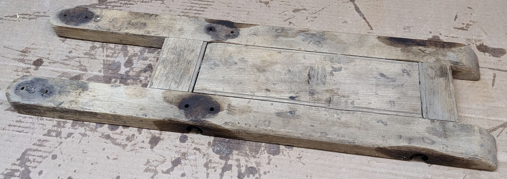
The base of the boring machine purchased by the author had been mostly stripped of its original varnish and covered with mud, and the rear short piece was slightly loose. Murphy’s Oil Soap quickly removed the mud, after which it was obvious that the wood was very dry and, well, old. Figure 5 shows the base at this stage of restoration. The author wanted to tighten the threaded rods to resolve the loose piece, but repeated application of PB Blaster and Freeze Off over most of a week did not loosen the rust between the nuts and the threaded rods. Although it was tempting to replace the current threaded rods with new ones to tighten the frame, the base seemed sufficiently solid to be used as-is.
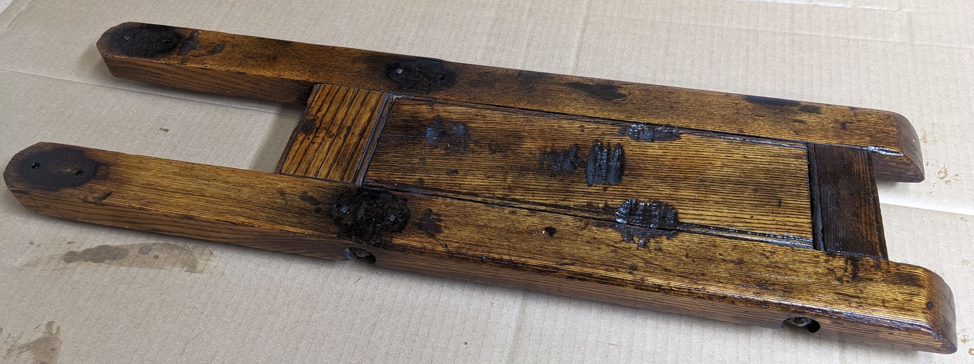
Moreover, the author had decided that he would make a new base in the future and avoid the immediate delay caused by replacing the threaded rods now, which would be wasted effort once the new base was constructed. For now, the base was sanded, and a finish was applied for aesthetics and, more importantly, to give the wood more integrity. The homemade finish consisted of equal parts of Turpentine, Boiled Linseed Oil, and Spar Varnish. The finished based is shown in Figure 6.
Making a new base is straightforward when you have an existing base that serves as a template. If you do not have a base, designs are posted on the Internet⁴,⁵.
Boring Mechanism Restoration
Most of the boring mechanism steel parts had little rust. Some exceptions were toward the base, specifically around the mounting brackets for the angled support rods and where the crank arms attached to the horizontal drive shaft. The machine also was caked with years of dried grease that had flowed out from between the surfaces that moved against each other. The steps below were followed to clean and disassemble the machine and are explained subsequently.
- Initial removal of caked, dried grease.
- Apply rust penetrant to free rusted fasteners.
- Disassemble.
- Degrease and clean parts.
- Lubricate and reassemble.
1. Initial Removal of Dirt and Grease
The author used carburetor cleaner with a brass wire brush and sometimes a putty knife to remove as much of the dried grease and dirt as possible. Besides the overall removal of grease, cleaning in this stage was focused in the proximity of fasteners to permit rust penetrant to be applied directly to machine screws and bolts to free them for disassembly. The author has used carburetor cleaner successfully in similar cleanups, such as freeing the ratchet mechanism of a bit brace that had not been used in at least 70 years. Multiple applications were required to loosen the thick layer of dried, caked grease. Care should be taken when using a putty knife because it is difficult to discern between the removal of caked grease and japanning.
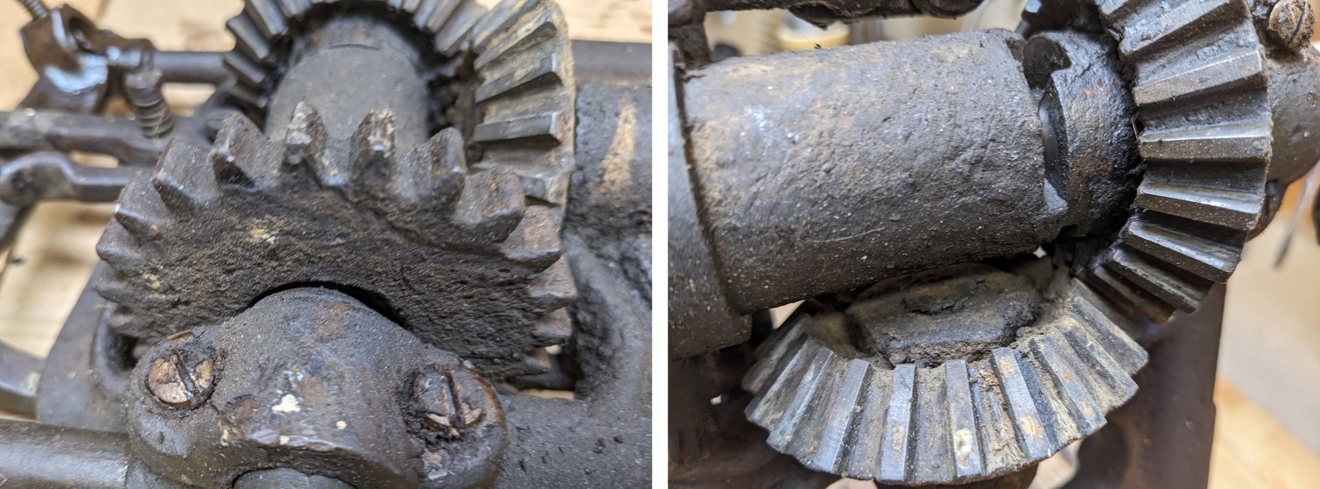
Figure 7 shows some of the remaining grease build-up after the initial removal.
2. Freeing Rusted Fasteners
PB Blaster and Freeze Off were used because the author has had success with on automotive projects with these products. Most screws were free after one application of solvent (and might have been free without any penetrant). Some fasteners required almost a week of repeated applications, so beware that patience is required here. It is best to budget multiple days or a week for such a project to recognize the possible waiting time for fasteners to be freed. Being patient is, in the author’s opinion, a worthwhile investment to preserve original fasteners and avoid the search for hard-to-find parts when fasteners are damaged or destroyed as they are removed.
3. Disassembly
Most parts are disassembled by loosening machine screws, while some parts, such as crank arms and some gears, are attached to shafts with (taper) pins that were removed with a 3/16” punch. These pins were removed easily, although careful observation of the pins is required to determine with end has a small diameter and which has a larger diameter because the pins will come out in only one direction.
4. Degreasing
Consistent with the goal of retaining as much of the paint as was possible, the author used Simple Green to remove the remaining grease and dirt on the disassembled parts, which is advertised to be paint safe. Parts were soaked in Simple Green for as long as necessary and brushed, most often, with a brass wire brush and sometimes a toothbrush. Multiple soakings with intervening brushing were sometimes required. Simple Green requires a water rinse after its application, so parts were thoroughly dried, and a light oil was applied (3-in-One Oil) to bare metal surfaces to inhibit rust prior to reassembly. Any light oil (e.g., Jojoba, Camelia) should also serve this purpose. A more aggressive approach to machine renovation might use alternative degreasers that may not be paint-safe, such as Purple Power or Degreaser/Cleaner by POR 15 and a powered steel wire brush wheel.
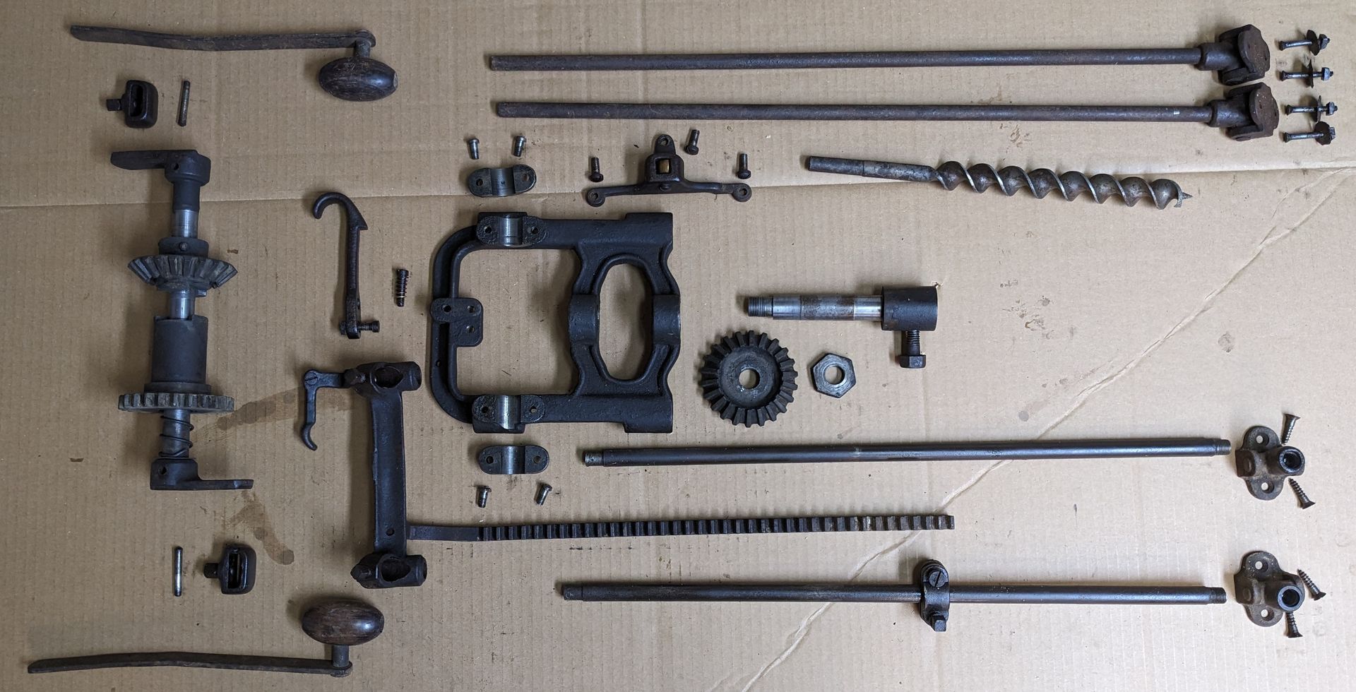
The disassembled and cleaned parts are shown in
Figure 8 prior to reassembly. Note that disassembly of some parts was not successful, including removal of the crank arms from the driven horizontal shaft and the screw that holds the rack gear for the extraction function onto the top horizontal frame piece. These parts defied disassembly even after soaking in PB Blaster and Freeze Off for nearly a week. In an effort to put the machine to work sooner rather than later, these areas of the machine were cleaned without disassembling them. In the case of the horizontal driven shaft, this necessitated a different cleaning approach as described later. These stubborn parts will be dealt with in the subsequent restoration.
5. Reassembly
Fasteners were reinstalled using Loctite 466863 Paste Anti-Seize Lubricant. Although the author intends to disassemble the machine soon for a more exhaustive restoration, the anti-seize paste still might ease the coming disassembly of the machine.
Two lubricants were used at reassembly: Lubriplate No. 130-AA and 3-in-One Oil. Lubriplate No. 130-AA was used as a lubricant on gears and between the bushing blocks and shafts. Lubriplate seemed well suited for these locations based on the manufacturer’s description of it as having “extremely good water repellency” and as being appropriate for “plain bearings, cams, guides, open gears, slides and chassis lubrication and where temperatures do not exceed 170°F.” Many greases might work well in these locations, but the author had good success with Lubriplate on automotive applications. A light oil like 3-in-One would likely work in these locations but the more viscous Lubriplate might better tend to remain within the moving surfaces, thus reducing the chance of the lubricant dripping from the machine onto its user and the timbers.
3-in-Oil was used on the slides and bushings of the boring carriage as well as on the roller bearing for the extraction mechanism rack gear. A light coat of 3-in-One Oil on the slides might be less messy than exposed grease. Time will reveal the effectiveness of this lubrication scheme.
- Antique Beam Drill [Restoration], https://www.youtube.com/watch?v=Ia_U4dKsZK0.
- Great Plains Craftsman: https://www.youtube.com/watch?v=7wfei1vpl8I, https://www.youtube.com/watch?v=2teDgvy11lc.
- Land to Sea: https://www.youtube.com/watch?v=TK2hApmlDQw.
- The Year of Mud: https://theyearofmud.com/2013/02/19/antique-millers-falls-boring-machine/ .
- Forestry Forum,
https://forestryforum.com/board/index.php?topic=62980.0.
If you have any inquiries or comments, you can contact the author at jrbrad314159@gmail.com
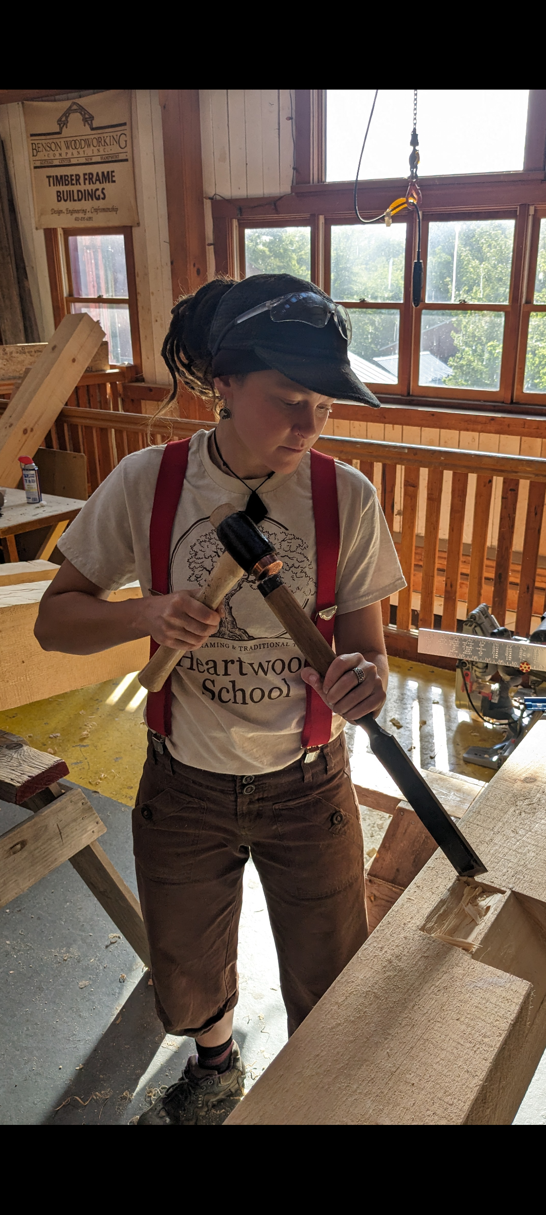
If you are interested in using historic tools, come learn to use a boring machine and more with us! Our Timber Framing courses focus on traditional methods using high quality historic and modern tools.
share this
Related Articles
Related Articles